Finding unknown sensors with I²C probing
The Mainline4Lumia project aims to bring mainline Linux to the Nokia/Microsoft Lumia phone series, which run a version of Windows Phone. We were making progress quickly, enabling I²C components such as the touchscreen and proximity/light sensor with information found in the stock UEFI tables. However, we couldn’t find any information regarding other sensors (accelerometer, gyroscope, magnetometer in the files; not even any GPIO references or I²C bus addresses. Unlike Android devices, which run a fork of the Linux kernel, we can’t go and look at the downstream kernel source - so I delved into the schematics to find out.
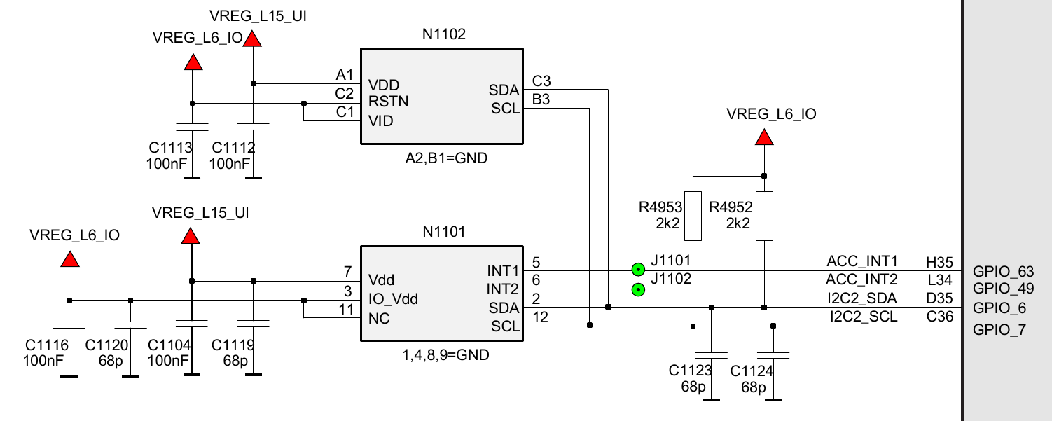
Schematics

This looked like it has the devices I was searching for. They were both wired up to I2C2, and the one with interrupts on GPIO_63 and GPIO_49 appeared to be an accelerometer (I assumed ACC was the abbreviation for it).
So, the information I knew so far:
Accelerometer
- Wired up to I2C2
- Two interrupts: INT1 on
GPIO_63and INT2 onGPIO_49 - Supplied by L15 (VDD) and L6 (VID)
Unknown device
- Wired up to I2C2
- No interrupts
- Supplied by L15 (VDD) and L6 (VDDIO)
This was not enough information to enable support for these devices in the Device Tree (.dts) files. I still didn’t know what I²C address they were at, which chips they were, and in the case of the second one what it actually was! It looked like I would have to manually poke I²C addresses…
I²C Probing
Prerequisites
Fortunately, such tools already existed - the aptly named i2c-tools collection, which contained:
- i2cdetect - detect I2C chips
- i2cdump - examine I2C registers
- i2cget - read from I2C/SMBus chip registers
- i2cset - set I2C registers
By enabling the I2C2 node in my device’s .dts file I could now probe it from userspace.
&blsp1_i2c2 {
    status = "okay";
};
I²C addresses
i2cdetect..dts is not the same as the I²C bus number that the i2c-tools suite expects. See the Linux I²C Interface Docs.$ sudo i2cdetect -y -r [number]
0 1 2 3 4 5 6 7 8 9 a b c d e f
00: -- -- -- -- 0c -- -- --
10: -- -- -- -- -- -- -- -- -- -- -- -- -- -- 1e --
20: -- -- -- -- -- -- -- -- -- -- -- -- -- -- -- --
30: -- -- -- -- -- -- -- -- -- -- -- -- -- -- -- --
40: -- -- -- -- -- -- -- -- -- -- -- -- -- -- -- --
50: -- -- -- -- -- -- -- -- -- -- -- -- -- -- -- --
60: -- -- -- -- -- -- -- -- -- -- -- -- -- -- -- --
70: -- -- -- -- -- -- -- --
Our two sensors are located at 0x0c and 0x1e, so now I know what addresses to poke.
To find out which devices are actually located at these addresses, I used i2cdevices.org to find out which I²C devices are known to reside at a specific address.
0x0c
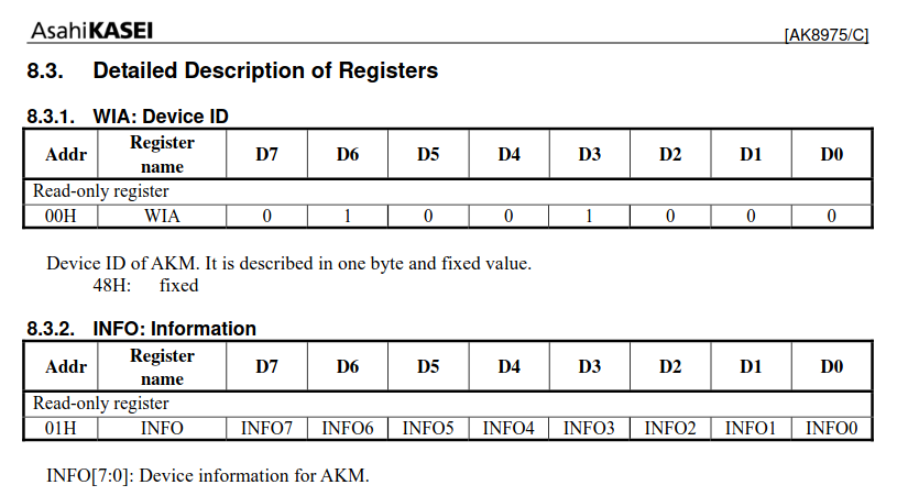
According to i2cdevices, 0x0c is where Asahi Kasei’s magnetometers are known to be. To verify this, I enlisted the help of another tool: i2cget. First, I looked up the WHO_AM_I register in the datasheet.
 Asahi Kasei I²C devices should read
 0x48 from the 0x00 register. So I tested this out:
$ sudo i2cget -y [number] 0x0c 0x00
0x48
It indeed read 0x48 from 0x00. So I tested out the INFO register, 0x01.
$ sudo i2cget -y [number] 0x0c 0x01
0x05
So which Asahi Kasei magnetometer was it then? I opened up Linux’s ak8975.c driver (which actually supports quite a few Asahi Kasei magnetometers, not just the AK8975) and lo and behold:
#define AK09916_DEVICE_ID		0x09
#define AK09912_DEVICE_ID		0x04
#define AK09911_DEVICE_ID		0x05
It was an Asahi Kasei AK09911.
&blsp1_i2c2 {
    status = "okay";

    ak09911: magnetometer@c {
		compatible = "asahi-kasei,ak09911";
		reg = <0x0c>;

		vdd-supply = <&pm8226_l15>;
		vid-supply = <&pm8226_l6>;
	};
};
I added the highlighted code to the device tree, rebuilt, and checked that the magnetometer was working by checking the values in the iio bus sysfs:
$ cat /sys/bus/iio/devices/iio\:device2/in_magn_x_raw
7
[rotate phone]
$ cat /sys/bus/iio/devices/iio\:device2/in_magn_x_raw
12
Now that was done and dusted, I moved on to the accelerometer.
0x1e
Unfortunately, i2cdevices.org this time didn’t show any devices known to be at 0x1e that were just accelerometers. There were accelerometer+magnetometer modules listed, but none on their own. I would have to use a different source - existing device trees in the Linux kernel source.
$ grep -rn arch/arm64/boot/dts -e '<0x1e>' -B 2
arch/arm64/boot/dts/allwinner/sun50i-a64-pinephone.dtsi-180-    lis3mdl: magnetometer@1e {
arch/arm64/boot/dts/allwinner/sun50i-a64-pinephone.dtsi-181-            compatible = "st,lis3mdl-magn";
arch/arm64/boot/dts/allwinner/sun50i-a64-pinephone.dtsi:182:            reg = <0x1e>;
--
arch/arm64/boot/dts/freescale/fsl-ls1046a-frwy.dts-154-
arch/arm64/boot/dts/freescale/fsl-ls1046a-frwy.dts-155-         qsgmii_phy3: ethernet-phy@1e {
arch/arm64/boot/dts/freescale/fsl-ls1046a-frwy.dts:156:                 reg = <0x1e>;
--
arch/arm64/boot/dts/freescale/fsl-ls1088a-rdb.dts-115-  mdio1_phy3: ethernet-phy@1e {
arch/arm64/boot/dts/freescale/fsl-ls1088a-rdb.dts-116-          interrupts-extended = <&extirq 1 IRQ_TYPE_LEVEL_LOW>;
arch/arm64/boot/dts/freescale/fsl-ls1088a-rdb.dts:117:          reg = <0x1e>;
--
arch/arm64/boot/dts/freescale/fsl-lx2162a-qds.dts-99-
arch/arm64/boot/dts/freescale/fsl-lx2162a-qds.dts-100-          mdio@1e { /* Slot #7 */
arch/arm64/boot/dts/freescale/fsl-lx2162a-qds.dts:101:                  reg = <0x1e>;
--
arch/arm64/boot/dts/freescale/imx8mq-librem5-devkit.dts-514-    magnetometer@1e {
arch/arm64/boot/dts/freescale/imx8mq-librem5-devkit.dts-515-            compatible = "st,lsm9ds1-magn";
arch/arm64/boot/dts/freescale/imx8mq-librem5-devkit.dts:516:            reg = <0x1e>;
--
arch/arm64/boot/dts/freescale/fsl-ls1012a-rdb.dts-44-   accelerometer@1e {
arch/arm64/boot/dts/freescale/fsl-ls1012a-rdb.dts-45-           compatible = "nxp,fxos8700";
arch/arm64/boot/dts/freescale/fsl-ls1012a-rdb.dts:46:           reg = <0x1e>;
--
arch/arm64/boot/dts/freescale/imx8mq-librem5.dtsi-885-  magnetometer@1e {
arch/arm64/boot/dts/freescale/imx8mq-librem5.dtsi-886-          compatible = "st,lsm9ds1-magn";
arch/arm64/boot/dts/freescale/imx8mq-librem5.dtsi:887:          reg = <0x1e>;
--
arch/arm64/boot/dts/freescale/fsl-ls1088a-ten64.dts-200-
arch/arm64/boot/dts/freescale/fsl-ls1088a-ten64.dts-201-        mdio1_phy3: ethernet-phy@1e {
arch/arm64/boot/dts/freescale/fsl-ls1088a-ten64.dts:202:                reg = <0x1e>;
--
arch/arm64/boot/dts/nvidia/tegra210-smaug.dts-1316-             ec@1e {
arch/arm64/boot/dts/nvidia/tegra210-smaug.dts-1317-                     compatible = "google,cros-ec-i2c";
arch/arm64/boot/dts/nvidia/tegra210-smaug.dts:1318:                     reg = <0x1e>;
--
arch/arm64/boot/dts/nvidia/tegra186-p2771-0000.dts-262-
arch/arm64/boot/dts/nvidia/tegra186-p2771-0000.dts-263-                         xbar_dspk1_port: port@1e {
arch/arm64/boot/dts/nvidia/tegra186-p2771-0000.dts:264:                                 reg = <0x1e>;
--
arch/arm64/boot/dts/nvidia/tegra194-p3509-0000.dtsi-225-
arch/arm64/boot/dts/nvidia/tegra194-p3509-0000.dtsi-226-                                        xbar_dspk1_port: port@1e {
arch/arm64/boot/dts/nvidia/tegra194-p3509-0000.dtsi:227:                                                reg = <0x1e>;
--
arch/arm64/boot/dts/nvidia/tegra210-p2371-2180.dts-977-
arch/arm64/boot/dts/nvidia/tegra210-p2371-2180.dts-978-                         xbar_amx1_in1_port: port@1e {
arch/arm64/boot/dts/nvidia/tegra210-p2371-2180.dts:979:                                 reg = <0x1e>;
--
arch/arm64/boot/dts/nvidia/tegra210-p3450-0000.dts-1352-
arch/arm64/boot/dts/nvidia/tegra210-p3450-0000.dts-1353-                                xbar_amx1_in1_port: port@1e {
arch/arm64/boot/dts/nvidia/tegra210-p3450-0000.dts:1354:                                        reg = <0x1e>;
--
arch/arm64/boot/dts/qcom/msm8916-huawei-g7.dts-105-     accelerometer@1e {
arch/arm64/boot/dts/qcom/msm8916-huawei-g7.dts-106-             compatible = "kionix,kx023-1025";
arch/arm64/boot/dts/qcom/msm8916-huawei-g7.dts:107:             reg = <0x1e>;
After finding all their specifications, none of them looked like it could be my accelerometer - except the last one. The Kionix KX023-1025, a three-axis accelerometer. I searched online for the datasheet and looked for the WHO_AM_I register.

So the KX023-1025 should report 0x15 from 0x0F.
$ i2cget -y [number] 0x1e 0x0f
0x14
Hmm.
So it isn’t the Kionix KX023-1025, but this 0x14 could mean something. I searched up Kionix WHO_AM_I 0x14h and the first result was the Kionix KX022-1020 datasheet. I eagerly opened it up, went to the WHO_AM_I register page, and there it was.

Linux didn’t seem to have a driver for the KX022-1020, but after skimming over both datasheets, they seemed similar enough.
I added a new accelerometer node in the .dts using the GPIO and supplier information I found previously, along with the I²C address and chip that I found here.
&blsp1_i2c2 {
    status = "okay";

    ak09911: magnetometer@c {
		compatible = "asahi-kasei,ak09911";
		reg = <0x0c>;

		vdd-supply = <&pm8226_l15>;
		vid-supply = <&pm8226_l6>;
	};

    kx022_1020: accelerometer@1e {
        /*
         * This is actually the Kionix KX022-1020, but the KX023-1025 driver
         * seems to work fine for now.
         */
        compatible = "kionix,kx023-1025";
        reg = <0x1e>;

        interrupt-parent = <&tlmm>;
        interrupts = <63 IRQ_TYPE_EDGE_RISING>;

        vdd-supply = <&pm8226_l15>;
        vddio-supply = <&pm8226_l6>;
    };
};
To test, I used the iio-sensor-proxy and monitor-sensor programs.
$ sudo service iio-sensor-proxy start
 * Starting iio-sensor-proxy ... [ ok ]

$ monitor-sensor
    Waiting for iio-sensor-proxy to appear
+++ iio-sensor-proxy appeared
=== Has accelerometer (orientation: normal)
=== Has ambient light sensor (value: 38.000000, unit: lux)
=== No proximity sensor
[rotate phone clockwise 360 degrees]
    Accelerometer orientation changed: normal
    Accelerometer orientation changed: right-up
    Accelerometer orientation changed: bottom-up
    Accelerometer orientation changed: left-up
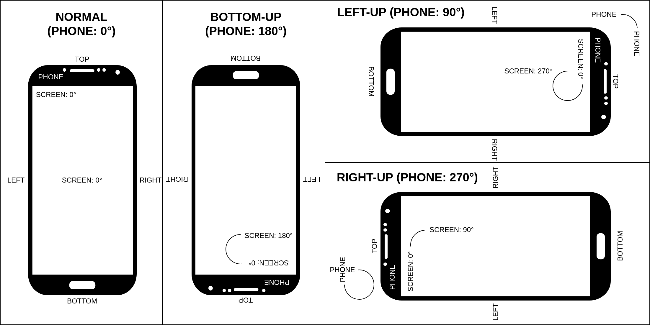
All seemed to be well, except the right-up and left-up orientations were switched. An diagram of these orientations is below.

This was fixed by using Linux’s mount-matrix in the device tree. An explanation of these mount-matrices can be found here.
The mount-matrix that I needed was this:
mount-matrix =  "1",  "0",  "0",
                "0", "-1",  "0",
                "0",  "0",  "1";
This mount-matrix negated the y reading, leading monitor-sensor to report the correct orientations.
$ monitor-sensor
    Waiting for iio-sensor-proxy to appear
+++ iio-sensor-proxy appeared
=== Has accelerometer (orientation: normal)
=== Has ambient light sensor (value: 19.000000, unit: lux)
=== No proximity sensor
[rotate phone clockwise 360 degrees]
    Accelerometer orientation changed: normal
    Accelerometer orientation changed: left-up
    Accelerometer orientation changed: bottom-up
    Accelerometer orientation changed: right-up
Final DTS node
&blsp1_i2c2 {
    status = "okay";

    ak09911: magnetometer@c {
		compatible = "asahi-kasei,ak09911";
		reg = <0x0c>;

		vdd-supply = <&pm8226_l15>;
		vid-supply = <&pm8226_l6>;
	};

    kx022_1020: accelerometer@1e {
        /*
         * This is actually the Kionix KX022-1020, but the KX023-1025 driver
         * seems to work fine for now.
         */
        compatible = "kionix,kx023-1025";
        reg = <0x1e>;

        interrupt-parent = <&tlmm>;
        interrupts = <63 IRQ_TYPE_EDGE_RISING>;

        vdd-supply = <&pm8226_l15>;
        vddio-supply = <&pm8226_l6>;

        mount-matrix =  "1",  "0",  "0",
                        "0", "-1",  "0",
                        "0",  "0",  "1";
    };
};
Now that the sensor collection is complete, we’re looking into enabling features such as charging, WiFi and camera. Once more progress is made, there’ll be more Lumia-related articles here! ;-)